
Page 228 - Modular design for machine tools
P. 228
188 Engineering Design for Machine Tool Joints
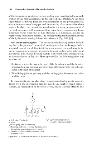
of the hydrostatic guideway in step loading was investigated in consid-
eration of the fluid capacitance in the oil feed line. Obviously, the fluid
capacitance is derived from the compressibility of the pressurized oil,
elastic deformation of the pipe, and intermixing of air across the whole
system. In short, the ratio of the overshoot to the steady displacement of
the table increases with increasing fluid capacitance in piping and has a
maximum value when the oil film stiffness is a maximum. Within an
engineering calculation context, the corresponding mathematical model
of the hydrostatic bearing follows that shown in Fig. 5-11 [13].
Main spindle-bearing system. The main spindle-bearing system includ-
ing the table system of the vertical turning machine can be regarded as
a special case of the sliding joint. In other words, the guideway is for
linear movement, whereas the spindle-bearing system is for rotational
movement. The spindle-bearing system is of complicated configuration,
as already shown in Fig. 5-4. More specifically, the following joints can
be observed.
1. Stationary joints between the wall of the headstock and the bearing
housing, bearing housing and outer race of bearing, both the side sur-
faces of the nut and spacer
2. The sliding joint at gearing and the rolling joint between the roller
and its races
In these joints, we can also observe some new developments in accor-
dance with the increasing spindle speed, i.e., higher- speed spindle
system, as exemplified by the step sleeve, which is press-fitted to the
P
m
x
c v
c T k L k K * x*
k *: Equivalent spring constant
x: Deflection of spring k L k
m: Mass caused by oil compressibility
k :Static spring constant of bearing
L
c : Damping coefficient of bearing depending upon
T
dimensional specifications and oil viscosity
c :Damping coefficient of bearing caused by oil
v
supplying system
Figure 5-11 A mathematical model of hydrostatic bearing.