
Page 230 - Modular design for machine tools
P. 230
190 Engineering Design for Machine Tool Joints
5.2 Definition of Machine Tool Joint and
Representation of Joint Characteristics
Although many studies of the joint have been carried out since 1939, it
is difficult to exactly define what the joint is and to determine where the
region of joint is. Intuitively, an acceptable definition is that the joint is
a portion of roughness and/or flatness deviation of the two surfaces in
contact, but this idea is not applicable, because of the evidence obtained
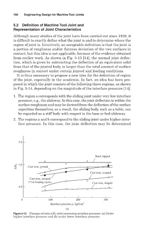
from earlier work. As shown in Fig. 5-13 [14], the normal joint deflec-
tion, which is given by subtracting the deflection of an equivalent solid
from that of the jointed body, is larger than the total amount of surface
roughness in contact under certain jointed and loading conditions.
It is thus necessary to propose a new idea for the definition of region
of the joint, especially in the academia. In fact, an idea has been pro-
posed in which the joint consists of the following three regions, as shown
in Fig. 5-14, depending on the magnitude of the interface pressure [14].
1. The region a corresponds with the sliding joint under very low interface
pressure, e.g., the slideway. In this case, the joint deflection is within the
surface roughness and may be derived from the deflection of the surface
asperities themselves; as a result, the sliding body, such as a table, can
be regarded as a stiff body with respect to the base or bed slideway.
2. The regions a and b correspond to the sliding joint under higher inter-
face pressure. In this case, the joint deflection may be determined
5.0
Steel, lapped
λ/R T 3.0 Cast iron, ground
Cast iron, scraped
Cast iron, scraped
(*1st loading cycle) Cast iron, shaped
1.0
0 100 200 300
Interface pressure p, kgf/cm 2
(a)
Figure 5-13 Changes of ratio /R T with increasing interface pressure: (a) Under
higher interface pressure and (b) under lower interface pressure.