Page 234 - Modular design for machine tools
P. 234

194   Engineering Design for Machine Tool Joints

                                                                      F y
                              y
                           x   z
                                                                        M xz
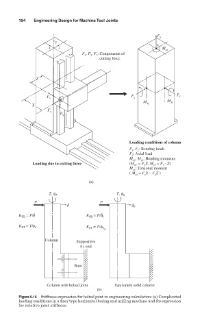
                                        F , F y , F z : Components of
                                         x
                                                         cutting force


                      Z


                                                            F                 F x
                          F x                                z
                                                                M xy      M yz
                     X
                           F z
                                F y


                                                           Loading conditions of column
                                                              z
                                                           F x , F : Bending loads
                                                           F : Axial load
                                                            y
                                                           M , M : Bending moments
                                                            xy
                                                               yz
                     Loading due to cutting force          (M  = F X, M  = F  · Z)
                                                                    yz
                                                                 y
                                                                        y
                                                             xy
                                                           M : Torsional moment
                                                            xz
                                                           ( M = F X – F Z )
                                                                     x
                                                             xz
                                                                 z
                                           (a)
                           T, f T                     T, f 0
                      P                        P
                                  d                         d 0
                   = P/d                  K  = P/d
               K SB                        0B   0
               K  = T/f T                 K  = T/f
                ST
                                                T
                                           0T
                                                 0
                          Column      Suppositive
                                        fix end
                                     Base
                          Column with bolted joint   Equivalent solid column
                                              (b)
               Figure 5-16 Stiffness expression for bolted joint in engineering calculation: (a) Complicated
               loading conditions in a floor type horizontal boring and milling machine and (b) expression
               for relative joint stiffness.
   229   230   231   232   233   234   235   236   237   238   239