
Page 239 - Modular design for machine tools
P. 239
Basic Knowledge of Machine Tool Joints 199
publicized elsewhere. It is furthermore emphasized that the joint stiff-
ness reduces considerably when the external load or due reaction force
at the joint is associated with the shear action.
Second, the relative displacement between the tool and the workpiece
due to the joint deflection is duly enlarged by the structural component,
when it behaves as a lever, as already shown in Fig. 5-2. In this case,
the deflection at the loading point can be obtained by multiplying the
inclination angle of the joint by the length of column. This multiplica-
tion action of a structural body component is remarkable in most
machine tools, having a large influence upon the machining accuracy.
Obviously, the data concerning the stiffness deterioration are useful to
understand quickly the influence of the joint upon the overall stiffness.
In contrast, to observe the joint characteristics in detail, it is necessary
to simplify the joint configuration, and thus most of the earlier
researches into the joint were carried out with the simple, flat, and
small test specimens, which are a model of the actual joint.
In this context, note that the model theory for the machine tool would
not be completely applicable for the structure having the joint as
reported by Ito and Masuko [19]. In fact, they suggested that the model
theory can be applied to the structure with a joint, provided that the
length scale factor is more than one-third. Most of the earlier works are
thus not directly applicable to the design of the machine tool structure
in full-size, but are indirectly applicable.
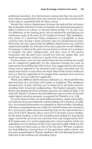
Third, joint stiffness shows nonlinear behavior; i.e., the load-deflection
characteristic of a structure with joints is nonlinear. This nonlinear
characteristic of joint stiffness can be observed in all joints notwith-
standing their structural configurations. Two typical examples classi-
fied by the magnitude of the interface pressure are shown in Figs. 5-19
and 5-20. Figure 5-19 shows the load-deflection characteristic of the joint
under higher interface pressure as reported by Thornley et al. [15].
It can be observed that the joint deflection shows, along with nonlin-
ear behavior, hysteresis behavior during loading and unloading. In addi-
tion, the residual deformation can obviously be observed after unloading.
A further interesting behavior is that the load-deflection characteristics
for a given joint under maximum loading cycle can be represented by a
curve 0- A-C-E-F, showing also a curve 0- A-C-D under a lower loading.
In the lower loading, a curve for reloading and loading far beyond the
upper limit of the previous one coincides with that designated by D-C-
E-F. Importantly, it is worth suggesting that a linear portion within the
unloading curve is identical to that of an equivalent solid, which has the
same shape and dimension as that of the flat joint. Without exception,
the load-deflection characteristic of the equivalent solid is linear and
inversely proportional to Young’s modulus, also not showing hysteresis
behavior in the loading and unloading cycles.