
Page 238 - Modular design for machine tools
P. 238
198 Engineering Design for Machine Tool Joints
1. The bay-type flange is very popular, e.g., in designing the bolted joint
for integrating both the structural body components and the con-
necting mechanism of the ball screw to the table. In due course, the
flange variations, e.g., location of the connecting bolt, configuration
of the bay-type with or without rib, and bay-type with enclosed bolt
pocket, show the larger difference in the joint stiffness.
2. The deformation and vibration modes of the joint surroundings
are the leading factors in the determination of the damping
capacity.
3. The structural configuration has especially large effects on the inter-
face pressure distribution, resulting in the differing stiffness of the
joint.
5.4 Effects of Joint on Static and Dynamic
Stiffness, and Thermal Behavior of Machine
Tool as a Whole
According to long-standing experiences, the static stiffness of the joint
is, in general, very low compared with that of the structural body com-
ponent itself. As a result, the overall stiffness of a machine tool as a
whole deteriorates significantly, as already shown in Fig. 5-2. More
specifically, the jointed body structure shows the following characteristic
features under static loading.
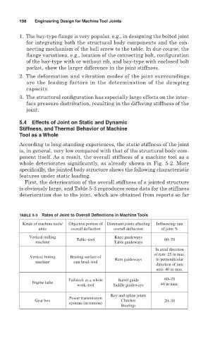
First, the deterioration of the overall stiffness of a jointed structure
is obviously large, and Table 5-3 reproduces some data for the stiffness
deterioration due to the joint, which are obtained from reports so far
TABLE 5-3 Rates of Joint to Overall Deflections in Machine Tools
Kinds of machine tools/ Objective portion of Dominant joints affecting Influencing rate
units overall deflection overall deflection of joint %
Vertical milling Knee guideways
machine Table–tool Table guideways 60–70
In axial direction
of ram: 25 in max.
Vertical boring Bearing surface of
Ram guideways In perpendicular
machine ram head–tool
direction of ram
axis: 40 in max.
Tailstock as a whole Barrel guide 60–70
Engine lathe 40 in max.
work–tool Saddle guideways
Key and spline joints
Power transmission
Gear box Clutches 20–30
systems (in torsion)
Bearings