
Page 241 - Modular design for machine tools
P. 241
Basic Knowledge of Machine Tool Joints 201
70
1 2 3 4 5 6 7 8
60
50
Pressure lb/in 2 40
30
20
10
0 20 40 60 80 100 120 140 160 180 200
Surface deflection, in × 10 –6
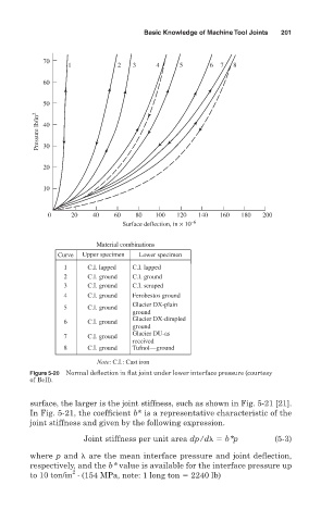
Material combinations
Curve Upper specimen Lower specimen
1 C.I. lapped C.I. lapped
2 C.I. ground C.I. ground
3 C.I. ground C.I. scraped
4 C.I. ground Ferobestos ground
Glacier DX-plain
5 C.I. ground
ground
Glacier DX-dimpled
6 C.I. ground
ground
Glacier DU-as
7 C.I. ground
received
8 C.I. ground Tufnol—ground
Note: C.I.: Cast iron
Figure 5-20 Normal deflection in flat joint under lower interface pressure (courtesy
of Bell).
surface, the larger is the joint stiffness, such as shown in Fig. 5-21 [21].
In Fig. 5-21, the coefficient b* is a representative characteristic of the
joint stiffness and given by the following expression.
Joint stiffness per unit area dp/d b*p (5-3)
where p and are the mean interface pressure and joint deflection,
respectively, and the b* value is available for the interface pressure up
2
to 10 ton/in (154 MPa, note: 1 long ton 2240 lb)