
Page 233 - Modular design for machine tools
P. 233
Basic Knowledge of Machine Tool Joints 193
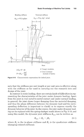
Bending stiffness Torsional stiffness
K SB = P/δ, kgf/mm K ST = T/ψ , kgf · m/rad
T
d
∆X φ
, T
ψ T
P
Column
H
∆φ
Base
∆X = H · ∆φ E: Young’s modulus
φ
PH 3 I: Cross-sectional
d = ∆X + moment of inertia
φ
3EI
Figure 5-15 Characteristic expressions for bolted joint.
note that the stiffness per unit length or per unit area is effective along
with the stiffness so far used in carrying out the research into and
design of the joint.
In contrast to static loading, there are certain kinds of difficulties in rep-
resenting the characteristics of the joint under dynamic loading. Apart
from the joint in real metal-to-metal contact and under normal loading,
in general, the joint shows larger damping than the material damping,
and thus the phase difference between the dynamic load and the corre-
sponding deflection is important to clarify or to express exactly the
dynamic behavior of the joint. In due course, the joint under dynamic load-
ing can be replaced with the spring-dashpot model shown in Fig. 5-18, and
using this model, the dynamic joint stiffness K dyn can be written as
K jK (5-1)
K dyn a b
where K is the in-phase stiffness and K is the quadrature stiffness
b
a
(damping-related stiffness).