
Page 186 - Multifunctional Photocatalytic Materials for Energy
P. 186
172 Multifunctional Photocatalytic Materials for Energy
hγ hγ
Dye sensitized Dye sensitized
TiO 2 nanoparticles TiO 2 nanotubes
Ti-substrate
(A) –1 e – Ti-substrate 0 e – (b) IMVS
Transport time constant (s) 10 –2 Recombination time constant (s) 10 –1
(a) IMPS
10
10
–3
10
Nanoparticle
Nanoparticle
10 15 Nanotube 10 16 10 17 10 –2 10 15 Nanotube 10 16 10 17
(B) Incident photon flux (cm s ) Incident photon flux (cm s )
–2 –1
–2 –1
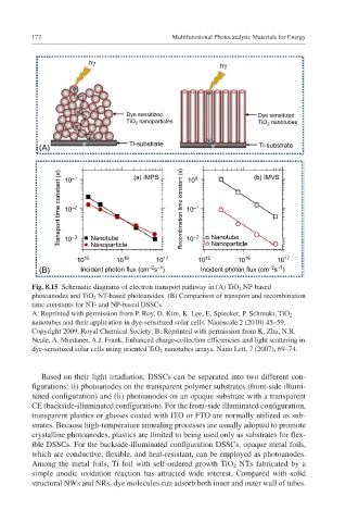
Fig. 8.15 Schematic diagrams of electron transport pathway in (A) TiO 2 NP-based
photoanodes and TiO 2 NT-based photoanodes. (B) Comparison of transport and recombination
time constants for NT- and NP-based DSSCs.
A: Reprinted with permission from P. Roy, D. Kim, K. Lee, E. Spiecker, P. Schmuki, TiO 2
nanotubes and their application in dye-sensitized solar cells. Nanoscale 2 (2010) 45–59.
Copyright 2009, Royal Chemical Society; B: Reprinted with permission from K. Zhu, N.R.
Neale, A. Miedaner, A.J. Frank, Enhanced charge-collection efficiencies and light scattering in
dye-sensitized solar cells using oriented TiO 2 nanotubes arrays. Nano Lett. 7 (2007), 69–74.
Based on their light irradiation, DSSCs can be separated into two different con-
figurations: (i) photoanodes on the transparent polymer substrates (front-side illumi-
nated configuration) and (ii) photoanodes on an opaque substrate with a transparent
CE (backside-illuminated configuration). For the front-side illuminated configuration,
transparent plastics or glasses coated with ITO or FTO are normally utilized as sub-
strates. Because high-temperature annealing processes are usually adopted to promote
crystalline photoanodes, plastics are limited to being used only as substrates for flex-
ible DSSCs. For the backside-illuminated configuration DSSCs, opaque metal foils,
which are conductive, flexible, and heat-resistant, can be employed as photoanodes.
Among the metal foils, Ti foil with self-ordered growth TiO 2 NTs fabricated by a
simple anodic oxidation reaction has attracted wide interest. Compared with solid
structural NWs and NRs, dye molecules can adsorb both inner and outer wall of tubes.