
Page 354 - Book Hosokawa Nanoparticle Technology Handbook
P. 354
FUNDAMENTALS CH. 6 EVALUATION METHODS FOR PROPERTIES OF NANOSTRUCTURED BODY
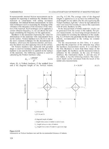
In nanomaterials, internal friction measurement can be (see Fig. 6.2.10). The average value of the diagonal
required for expecting to minimize the vibration of the lengths is applied as d, as we have two different diag-
materials or components with adding secondary onal lengths on one indent. For the unit expressing the
–2
nanophase. For internal friction measurement, we have Vickers hardness, kgf mm (force by kgf and area by
2
some techniques such as measuring the dumping of the mm ) was used, but recently we can see the expression
vibration or the sharpness of the resonance of the vibra- with SI units, hardness in GPa.
tion of the materials. Each technique can be applied at a In the measurement of brittle materials, cracks can
certain vibration frequency, so, we can choose the tech- be generated from the corner of the indents. For pre-
nique considering the frequency for the applications. cise measurement, we must keep enough distance on
Hardness is the parameter expressing the value for every indent for avoiding the influence of the cracks.
deformation of the materials with concentrated force Fig. 6.2.10 shows the guideline for the distance of the
on the surface. Vickers hardness test [10,11] is one of indents, recommended in the testing on ceramic
the most common technique for the measurement of materials.
hardness, which uses the diamond indenter, and meas- For the measurement on thin films, it is antici-
ures the indent size after applying force on the surface. pated that the properties of the substrate may affect
On Vickers hardness test, diamond with pyramid the hardness measurement results. It is said that if
shape is used for forming indents, and the tip of the the film thickness is more than three times of the
indenter is put and the force is applied on the surface indent depth, the hardness can be measured with no
of the materials. The following equation is used for influence by the substrate. In the case of Vickers
calculating the Vickers hardness value. hardness, the indentation depth, h, and the area of
the indent, S, has the following relation. The inden-
1 8544 P
.
H (6.2.6) tation depth can be calculated from the result of the
V
d 2 indent area measurement.
where, H is Vickers hardness, P the applied force
V
and d the diagonal length of the formed indents S 24.5 h 2 (6.2.7)
c
d
Specimen edge
L 2 L 1
L 1 4d and 5c
2.5d and 5c
L 2
d: diagonal length of indent
c: length form center of indent to end of crack
: length between center of indents
L 1
: length from center of indent to specimen edge
L 2
Figure 6.2.10
Indentation on Vickers hardness test and the recommended distance of indents.
328