
Page 356 - Book Hosokawa Nanoparticle Technology Handbook
P. 356
FUNDAMENTALS CH. 6 EVALUATION METHODS FOR PROPERTIES OF NANOSTRUCTURED BODY
size of the nanocrystalline material is very small, spe- shown in Fig. 6.2.13. The nominal stress on the sur-
cial testing which does not comply with the agreed face of the specimen is calculated by using the simple
standards is often performed to acquire data. beam theory
(a) Tensile creep test 3( PL ) l
(6.2.10)
For analysis of creep and creep rupture a test technique 2wt 2
is required which uses a specimen with a uniform, sta-
tionary stress distribution in its gauge length. This is
achieved in a tensile creep test most satisfactorily. In where P is the applied load, L the outer span length, l
Fig. 6.2.12 a tensile specimen with a circular cross the inner span length, w the specimen width, and t the
section is presented as an example. The gauge length specimen thickness. The nominal strain is calculated
from the specimen deflection
L of the specimen is measured by: (1) mechanical
strain extensometer or (2) optical strain extensometer.
Engineering stress or nominal stress is defined by 4t
(%) 100 (6.2.11)
l 2
P
(6.2.8)
A 0 This method is relatively easy to measure small strain,
but the simple beam theory is applicable only under
where A is the initial cross-sectional area prior to the following assumptions: (a) Creep behavior in tension
0
application of the load P. Engineering strain or nom- and compression is identical. (b) Friction at contact
inal strain is represented by points is negligible. (c) Creep behavior is Newtonian.
When the creep is non-Newtonian, the analysis of
(L L ) deformation is complicated due to the stress gradient
0 (6.2.9)
L 0 inside the specimen.
where L is the initial gauge length. 6.2.3.2 Superplasticity test
0
One of the major concerns in tensile creep appara- Tension and compression tests are performed at a con-
tus is specimen alignment to minimize bending stant displacement rate by using a universal test
moments that are introduced by the tensile load train. machine in order to determine superplastic forming
This requires the flexibility in the pull rods, that is a properties. Instead of engineering stress and engi-
flexible coupling, and a grip that transmits the load neering strain, true stress true strain curves are
t
t
through the geometric center of the specimen. obtained for large deformations
(b) Compressive creep test ⎛ L ⎞
ln ⎜ ⎟ (6.2.12)
The Uniaxial compression test is a useful procedure t ⎝ L ⎠
0
for measuring creep of a small nanocrystalline
specimen that has either cylindrical or square cross P L
section. In order to prevent buckling, specimens with (6.2.13)
t
length/diameter ratio 1 L/d 2 are used usually. A L 0
0
Barreling occurs when L/d 2 and friction is present
at the contact surface. Homogeneous deformation can
be achieved by using smooth surface without friction.
(c) Bending creep test
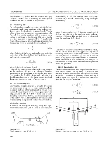
A method of four-point bending creep for high-
performance ceramics (JIS R 1612) is schematically
Grip Grip
D´
D
R2
R2
Gauge length L
Figure 6.2.12 Figure 6.2.13
Tensile creep specimen (JIS R 1631). Four-point bending creep test method (JIS R 1612).
330