
Page 352 - Book Hosokawa Nanoparticle Technology Handbook
P. 352
FUNDAMENTALS CH. 6 EVALUATION METHODS FOR PROPERTIES OF NANOSTRUCTURED BODY
[3] Y. Zhou, V. Rangari, H. Mahfuz, S. Jeelani and P.K.
Mallick: Mater. Sci. Eng. A, 402, 109–117 (2005).
[4] H.J. Hwang, K.-I. Tajima, M. Sando, M. Toriyama and
N. Niihara: J. Ceram. Soc. Jpn., 108, 339–344 (2000).
6.2.2 Elastic constants: hardness
For discussing elastic constants and hardness on
nanomaterials, instrumented hardness tester (or called
‘nano-indenter’) is an important equipment. It meas-
ures the relation between the indenting depth and the
applied force on the specimen, and the elastic con-
stants and the hardness can be calculated [1–4]. The
detail of this method is described in Section 6.2.5. In
this section, the outline of elastic constants and hard-
ness are explained.
Elastic constants are the parameters expressing the
relation between the stress and the strain on the mate-
rials within the stress range that the materials exhibit
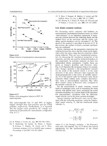
Figure 6.2.6 elastic behavior. They are very fundamental parame-
Fatigue behavior of polypropylene nanocomposites. ters for discussing the mechanical properties of the
materials, and they are used for numerical analysis of
the components. In isotropic material, we have two
independent elastic parameters. Usually, those are
given as Young’s modulus and Poisson’s ratio.
Fig. 6.2.8 illustrates the meanings of these two param-
eters. Young’s modulus is the proportional constant
for the strain of the material which is in the same
direction of the stress. Poisson’s ratio expresses the
strain perpendicular to the stress. In metallic materi-
als, 0.3 is the typical value for Poisson’s ratio, but in
materials which contain some complex microstruc-
ture, such as polycrystalline materials, they often
show smaller values of Poisson’s ratio, compared to
the metallic materials [5].
For the measurement of elastic constants, several
kinds of techniques exist, such as measuring the strain
directly with applied static stress, measuring the sound
resonance frequency on a certain shape of the specimen.
Figure 6.2.7 For nanomaterials, calculation from the ultrasonic
Fatigue crack propagation behavior of PZT–Pt sound velocity can be the most common technique.
nanocomposites. Young’s modulus and Poisson’s ratio can be calcu-
lated with the following equations, using the longitu-
The nanocomposite has 13 and 50% of higher dinal sound velocity, V and the transversal sound
L
fatigue strength than neat polymer and talc filled velocity, V .
T
polymer, respectively. Furthermore, it is reported
that the fatigue crack growth by AC voltage was 3 VV 4 V 4
2
2
restricted in piezoelectric nanoceramic composites E LT 2 T (6.2.1)
2
(Fig. 6.2.7). V V T
L
1 V L 2 2V T 2
References (6.2.2)
2 V L 2 V T 2
[1] K. Niihara: J. Ceram. Soc. Jpn., 99, 974–982 (1991).
[2] S. Kamiwaki, M. Iguchi, M. Hotta, J. Tatami, where E is the Young’s modulus, the Poisson’s
K. Komeya, T. Meguro, M. Omori and T. Hirai: ratio and the density. Fig. 6.2.9 shows the typical
Corrosion resistance of Ca- SiAlON nano ceramics: equipments for the measurement of the sound
Proceedings of 2nd MP3 176–183 (2004). velocity [6].
326