
Page 77 - New Trends In Coal Conversion
P. 77
Current status of CO 2 capture from coal facilities 43
Power
generation
Stack
Cyclones
Air reactor Loop Carbon Fuel reactor
stripper
seal
Loop Loop Steam
seal seal Flue gas desulfurization Condenser Purification unit
Particulate Coal
control
Air Steam
Ash Water
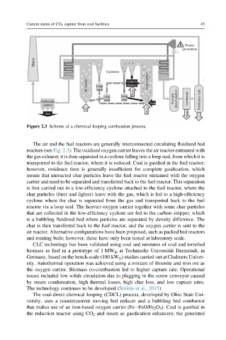
Figure 2.3 Scheme of a chemical looping combustion process.
The air and the fuel reactors are generally interconnected circulating fluidized bed
reactors (see Fig. 2.3). The oxidized oxygen carrier leaves the air reactor entrained with
the gas exhaust; it is then separated in a cyclone falling into a loop seal, from which it is
transported to the fuel reactor, where it is reduced. Coal is gasified in the fuel reactor;
however, residence time is generally insufficient for complete gasification, which
means that unreacted char particles leave the fuel reactor entrained with the oxygen
carrier and need to be separated and transferred back to the fuel reactor. This separation
is first carried out in a low-efficiency cyclone attached to the fuel reactor, where the
char particles (finer and lighter) leave with the gas, which is fed to a high-efficiency
cyclone where the char is separated from the gas and transported back to the fuel
reactor via a loop seal. The heavier oxygen carrier together with some char particles
that are collected in the low-efficiency cyclone are fed to the carbon stripper, which
is a bubbling fluidized bed where particles are separated by density difference. The
char is then transferred back to the fuel reactor, and the oxygen carrier is sent to the
air reactor. Alternative configurations have been proposed, such as packed bed reactors
and rotating beds; however, these have only been tested at laboratory scale.
CLC technology has been validated using coal and mixtures of coal and torrefied
biomass as fuel in a prototype of 1 MW th at Technische Universit€ at Darmstadt, in
Germany, based on the bench-scale (100 kW th ) studies carried out at Chalmers Univer-
sity. Autothermal operation was achieved using a mixture of ilmenite and iron ore as
the oxygen carrier. Biomass co-combustion led to higher capture rate. Operational
issues included low solids circulation due to plugging in the screw conveyor caused
by steam condensation, high thermal losses, high char loss, and low capture rates.
The technology continues to be developed (Str€ ohle et al., 2015).
The coal-direct chemical looping (CDCL) process, developed by Ohio State Uni-
versity, uses a countercurrent moving bed reducer and a bubbling bed combustor
that makes use of an iron-based oxygen carrier (FeeFeO/Fe 2 O 3 ). Coal is gasified in
the reduction reactor using CO 2 and steam as gasification enhancers; the generated