
Page 172 - Numerical Analysis and Modelling in Geomechanics
P. 172
MODELLING OF GROUND WAVES 153
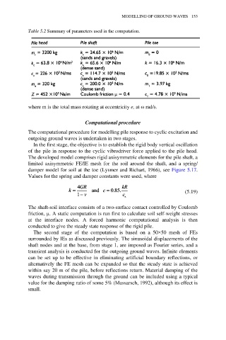
Table 5.2 Summary of parameters used in the computation.
where m is the total mass rotating at eccentricity e, at ω rad/s.
Computational procedure
The computational procedure for modelling pile response to cyclic excitation and
outgoing ground waves is undertaken in two stages.
In the first stage, the objective is to establish the rigid body vertical oscillation
of the pile in response to the cyclic vibrodriver force applied to the pile head.
The developed model comprises rigid axisymmetric elements for the pile shaft, a
limited axisymmetric FE/IE mesh for the soil around the shaft, and a spring/
damper model for soil at the toe (Lysmer and Richart, 1966), see Figure 5.17.
Values for the spring and damper constants were used, where
(5.19)
The shaft-soil interface consists of a two-surface contact controlled by Coulomb
friction, µ. A static computation is run first to calculate soil self-weight stresses
at the interface nodes. A forced harmonic computational analysis is then
conducted to give the steady state response of the rigid pile.
The second stage of the computation is based on a 50×50 mesh of FEs
surrounded by IEs as discussed previously. The sinusoidal displacements of the
shaft nodes and at the base, from stage 1, are imposed as Fourier series, and a
transient analysis is conducted for the outgoing ground waves. Infinite elements
can be set up to be effective in eliminating artificial boundary reflections, or
alternatively the FE mesh can be expanded so that the steady state is achieved
within say 20 m of the pile, before reflections return. Material damping of the
waves during transmission through the ground can be included using a typical
value for the damping ratio of some 5% (Massarsch, 1992), although its effect is
small.