
Page 180 - Numerical Analysis and Modelling in Geomechanics
P. 180
MODELLING OF GROUND WAVES 161
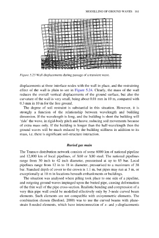
Figure 5.23 Wall displacements during passage of a transient wave.
displacements at three interface nodes with the wall in place, and the restraining
effect of the wall is plain to see in Figure 5.24. Clearly, the mass of the wall
reduces the overall vertical displacements of the ground surface, but also the
curvature of the wall is very small, being about 0.01 mm in 10 m, compared with
0.3 mm in 10 m for the free ground.
The degree of soil restraint is substantial in this situation. However, it is
strongly a function of the relationship between wavelength and building
dimension. If the wavelength is long, and the building is short the building will
‘ride’ the wave, in rigid-body pitch and heave, reducing soil movements because
of extra mass only. If the building is longer than the half-wavelength then the
ground waves will be much reduced by the building stiffness in addition to its
mass, i.e. there is significant soil-structure interaction.
Buried gas main
The Transco distribution network consists of some 6000 km of national pipeline
and 12,000 km of local pipelines, of X60 or X80 steel. The national pipelines
range from 30 inch to 42 inch diameter, pressurised at up to 85 bar. Local
pipelines range from 12 in to 18 in diameter, pressurised to a maximum of 38
bar. Standard depth of cover to the crown is 1.1 m, but pipes may run at 3 m, or
exceptionally at 10 m in locations beneath embankments or buildings.
The situation was analysed where piling took place to one side of a pipeline,
and outgoing ground waves impinged upon the buried pipe, causing deformation
of the thin wall of the pipe cross-section. Realistic bending and compression of a
very thin pipe wall could be modelled effectively only by 3-node curved beam
elements. Such elements are not compatible with axisymmetric elements. The
combination chosen (Besford, 2000) was to use the curved beams with plane-
strain 8-noded elements, which have interconnection of x- and y-displacements