
Page 178 - Numerical Analysis and Modelling in Geomechanics
P. 178
MODELLING OF GROUND WAVES 159
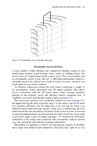
Figure 5.21 Schematic view of soil plus structure.
Rectangular steel portal frame
A large number of light industrial and commercial buildings consist of steel
portal frames founded on pad footings, with a variety of cladding options. The
natural choice of computational model is plane stress. This is incompatible with
an axisymmetric model of pile and soil. A fully three-dimensional solution is
unsuitable because the solution time would be totally excessive, and mesh size
would suffer for any realistic solution.
An effective compromise solution has been found, comprising a ‘wedge’ of
the axisymmetric model, represented with 3D fanned elements. This allows
correct connectivity with the 2D portal frame, whilst ensuring geometric
damping of the outgoing waves, and allowing realistic computing time. A
simplified view of the soil-structure system is shown in Figure 5.21.
The mesh used in practice was considerably refined from that in Figure 5.21.
For impact driving the mesh represents stage 3 of the model, and the FE mesh
was extended sufficiently that the behaviour of the soil and the frame were
identified before reflections had returned. In the case of vibrodriving, IEs were
added around the outer boundaries. Excitation of the system in terms of transient
or sinusoidal displacements was imposed onto the inner curved face of the mesh,
as derived by stages 1 and 2 for impact and stage 1 for vibrodriving. Preliminary
calibrations of the wedge mesh compared with axisymmetric analyses showed
very close agreement, with effective geometric attenuation.
The method was applied to a uniform soil with dynamic modulus of 200 MPa,
and a single steel portal on pad foundations. The portal had a span of 12.5 m,