
Page 179 - Numerical Analysis and Modelling in Geomechanics
P. 179
160 C.L.RAMSHAW AND A.R.SELBY
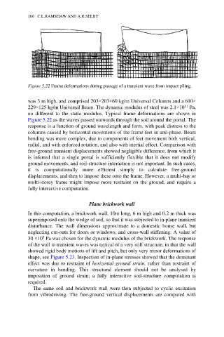
Figure 5.22 Frame deformations during passage of a transient wave from impact piling.
was 3 m high, and comprised 203×203×60 kg/m Universal Columns and a 610×
11
229×125 kg/m Universal Beam. The dynamic modulus of steel was 2.1×10 Pa,
no different to the static modulus. Typical frame deformations are shown in
Figure 5.22 as the waves passed outwards through the soil around the portal. The
response is a function of ground wavelength and form, with peak distress to the
columns caused by horizontal movements of the frame feet in anti-phase. Beam
bending was more complex, due to components of feet movement both vertical,
radial, and with enforced rotation, and also with inertial effect. Comparison with
free-ground transient displacements showed negligible difference, from which it
is inferred that a single portal is sufficiently flexible that it does not modify
ground movements, and soil-structure interaction is not important. In such cases,
it is computationally more efficient simply to calculate free-ground
displacements, and then to impose these onto the frame. However, a multi-bay or
multi-storey frame might impose more restraint on the ground, and require a
fully interactive computation.
Plane brickwork wall
In this computation, a brickwork wall, 10m long, 6 m high and 0.2 m thick was
superimposed onto the wedge of soil, so that it was subjected to in-plane transient
disturbance. The wall dimensions approximate to a domestic house wall, but
neglecting cut-outs for doors or windows, and cross-wall stiffening. A value of
9
30 ×10 Pa was chosen for the dynamic modulus of the brickwork. The response
of the wall to transient waves was typical of a very stiff structure, in that the wall
showed rigid body motions of lift and pitch, but only very minor deformations of
shape, see Figure 5.23. Inspection of in-plane stresses showed that the dominant
effect was due to restraint of horizontal ground strain, rather than restraint of
curvature in bending. This structural element should not be analysed by
imposition of ground strain; a fully interactive soil-structure computation is
required.
The same soil and brickwork wall were then subjected to cyclic excitation
from vibrodriving. The free-ground vertical displacements are compared with