
Page 48 - Numerical Analysis and Modelling in Geomechanics
P. 48
COMPRESSED AIR TUNNELLING 29
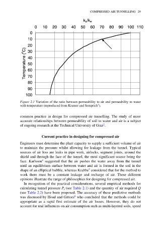
Figure 2.1 Variation of the ratio between permeability to air and permeability to water
3
with temperature (reproduced from Kramer and Semprich ).
common practice in design for compressed air tunnelling. The study of more
accurate relationships between permeability of soil to water and air is a subject
2
of ongoing research at the Technical University of Graz .
Current practice in designing for compressed air
Engineers must determine the plant capacity to supply a sufficient volume of air
to maintain the pressure whilst allowing for leakage from the tunnel. Typical
sources of air loss are leaks in pipe work, airlocks, segment joints, around the
shield and through the face of the tunnel, the most significant source being the
face. Karlsson 4 suggested that the air pushes the water away from the tunnel
until an equilibrium surface between water and air is formed in the soil in the
5
shape of an elliptical bubble, whereas Krabbe considered that for the method to
work there must be a constant leakage and recharge of air. These different
opinions illustrate the range of philosophies for designing for compressed air.
In recognition of the practical considerations, several empirical methods for
calculating tunnel pressure P (see Table 2.1) and the quantity of air required Q
t
(see Table 2.2) have been proposed. The accuracy of these predictive methods
6
was discussed by Hoad and Gittoes who concluded that the methods could be
appropriate as a rapid first estimate of the air losses. However, they do not
account for real influences on air consumption such as multi-layered soils, speed