
Page 49 - Numerical Analysis and Modelling in Geomechanics
P. 49
30 A.A.JAVADI
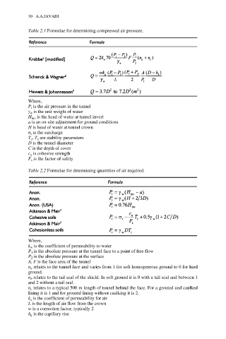
Table 2.1 Formulae for determining compressed air pressure.
Where,
P t is the air pressure in the tunnel
γ w is the unit weight of water
H inv is the head of water at tunnel invert
a is an on-site adjustment for ground conditions
H is head of water at tunnel crown
σ s is the surcharge
T c , T γ are stability parameters
D is the tunnel diameter
C is the depth of cover
c u is cohesive strength
F s is the factor of safety
Table 2.2 Formulae for determining quantities of air required.
Where,
k w is the coefficient of permeability to water
P 1 is the absolute pressure at the tunnel face to a point of free flow
P 2 is the absolute pressure at the surface
A, F is the face area of the tunnel
n a relates to the tunnel face and varies from 1 for soft homogeneous ground to 0 for hard
ground.
n b relates to the tail seal of the shield. In soft ground it is 0 with a tail seal and between 1
and 2 without a tail seal.
n c relates to a typical 500 m length of tunnel behind the face. For a grouted and caulked
lining it is 1 and for grouted lining without caulking it is 2.
k a is the coefficient of permeability for air
L is the length of air flow from the crown
w is a correction factor, typically 2
h k is the capillary rise