
Page 465 - Numerical Methods for Chemical Engineering
P. 465
454 9 Fourier analysis
k i A 1 B 1
1
k s
R = R – R 1
2
21
incident
wave
scattered
k i wave
2 E (r, t)
1
A 2 B 2
k s
scattered
wave
E (r, t)
2
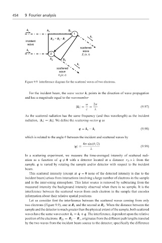
Figure 9.9 Interference diagram for the scattered waves of two electrons.
For the incident beam, the wave vector k i points in the direction of wave propagation
and has a magnitude equal to the wavenumber
ω 2π
|k i |= = (9.97)
c λ
As the scattered radiation has the same frequency (and thus wavelength) as the incident
radiation, |k s |=|k i |. We define the scattering vector q as
(9.98)
q = k s − k i
which is related to the angle θ between the incident and scattered waves by
4π sin (θ/2)
|q|= (9.99)
λ
In a scattering experiment, we measure the time-averaged intensity of scattered radi-
ation as a function of q = 0 with a detector located at a distance r D » λ from the
sample. q is varied by rotating the sample and/or detector with respect to the incident
beam.
This scattered intensity (except at q = 0 none of the detected intensity is due to the
incident beam) arises from interactions involving a large number of electrons in the sample
and in the intervening atmosphere. This latter source is removed by subtracting from the
measured intensity the background intensity observed when there is no sample. It is the
interference between the scattered waves from each electron in the sample that encodes
information about their relative spatial positions.
Let us consider first the interference between the scattered waves coming from only
two electrons (Figure 9.9), one at R 1 and the second at R 2 . When the distance between the
sample and the detector is much greater than the physical extent of the sample, both scattered
waves have the same wavevector k s = k i + q. The interference, dependent upon the relative
position of the electrons R 21 = R 2 − R 1 , originates from the different path lengths traveled
by the two waves from the incident beam source to the detector; specifically the difference