
Page 235 - Offshore Electrical Engineering Manual
P. 235
222 CHAPTER 4 Busbar Protection
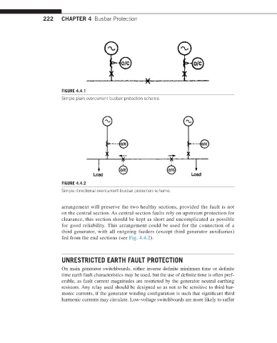
FIGURE 4.4.1
Simple plain overcurrent busbar protection scheme.
FIGURE 4.4.2
Simple directional overcurrent busbar protection scheme.
arrangement will preserve the two healthy sections, provided the fault is not
on the central section. As central section faults rely on upstream protection for
clearance, this section should be kept as short and uncomplicated as possible
for good reliability. This arrangement could be used for the connection of a
third generator, with all outgoing feeders (except third generator auxiliaries)
fed from the end sections (see Fig. 4.4.2).
UNRESTRICTED EARTH FAULT PROTECTION
On main generator switchboards, either inverse definite minimum time or definite
time earth fault characteristics may be used, but the use of definite time is often pref-
erable, as fault current magnitudes are restricted by the generator neutral earthing
resistors. Any relay used should be designed so as not to be sensitive to third har-
monic currents, if the generator winding configuration is such that significant third
harmonic currents may circulate. Low-voltage switchboards are more likely to suffer