
Page 375 - Offshore Electrical Engineering Manual
P. 375
362 CHAPTER 4 Protection and Control
A
B
C
V 2
V 1
V
Battery 1
V 2
– A +
Switch
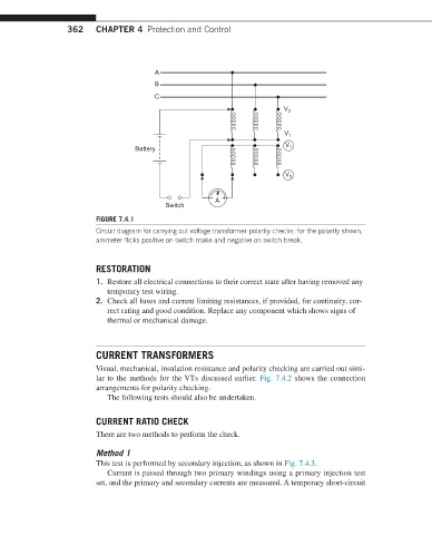
FIGURE 7.4.1
Circuit diagram for carrying out voltage transformer polarity checks: for the polarity shown,
ammeter flicks positive on switch make and negative on switch break.
RESTORATION
1. Restore all electrical connections to their correct state after having removed any
temporary test wiring.
2. Check all fuses and current limiting resistances, if provided, for continuity, cor-
rect rating and good condition. Replace any component which shows signs of
thermal or mechanical damage.
CURRENT TRANSFORMERS
Visual, mechanical, insulation resistance and polarity checking are carried out simi-
lar to the methods for the VTs discussed earlier. Fig. 7.4.2 shows the connection
arrangements for polarity checking.
The following tests should also be undertaken.
CURRENT RATIO CHECK
There are two methods to perform the check.
Method 1
This test is performed by secondary injection, as shown in Fig. 7.4.3.
Current is passed through two primary windings using a primary injection test
set, and the primary and secondary currents are measured. A temporary short-circuit