
Page 376 - Offshore Electrical Engineering Manual
P. 376
Current Transformers 363
P 2 CT P 1
– S 2 S 1 +
– +
A
Battery Switch
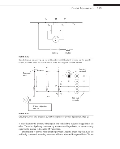
FIGURE 7.4.2
Circuit diagram for carrying out current transformer (CT) polarity checks: for the polarity
shown, ammeter flicks positive on switch make and negative on switch break.
A B C
Test plug
insulation
Temporary A 2
short 51
51
S 1
P 1 51
64
P 2 S 2
Test plug
A 1 contacts
Primary injection
test set
FIGURE 7.4.3
Circuit for current ratio check on current transformer by primary injection (method 1).
is placed across the primary windings at one end and the injection is applied at the
other. The ratio of primary to secondary ammeter readings should be approximately
equal to the marked ratio on the CT nameplate.
This method of current ratio test also provides a second check on polarity, as the
residually connected secondary ammeter will read a few milliamperes if the CTs are