
Page 381 - Offshore Electrical Engineering Manual
P. 381
368 CHAPTER 4 Protection and Control
Operating coil B phase
1 2 3 4 5 6 7 8
Test block terminals 9 10
(relay)
20 19 18 17 16 15 14 13 12 11
Test plug CT shorting links
terminals
1 2 3 4 5 6 7 89 10
A
Test block terminals
(supply)
Timer Relay
control current
Secondary injection unit
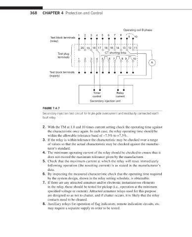
FIGURE 7.4.7
Secondary injection test circuit for triple-pole overcurrent and residually connected earth
fault relay.
2. With the TM at 1.0 and 10 times current setting check the operating time against
the characteristic once again. In each case, the relay operating time should be
within the allowable tolerance band of −7.5% to +7.5%.
3. If the relay is within tolerance the characteristic may be checked over a range
of values so that the actual characteristic may be checked against the manufac-
turer’s standard.
4. The minimum operating current of the relay should be checked to ensure that it
does not exceed the maximum tolerance given by the manufacturer.
5. Check that the maximum current at which the relay will reset immediately
following operation (the resetting current) is as stated in the manufacturer’s
data.
6. By inspecting the measured characteristic check that the operating time required
by the system design, shown in the relay setting schedule, is obtainable.
7. If there are any attracted armature and/or electronic instantaneous elements
in the relay, these should be tested for pickup (i.e., operation at the minimum
specified voltage or current). Attracted armature relays used for this purpose
are designed so as not to chatter, and if chatter occurs, it is likely that the relay
contacts need to be cleaned.
8. Auxiliary relays for operation of flag indicators, remote indication circuits, etc.
may require a separate supply in order to be tested.