
Page 377 - Offshore Electrical Engineering Manual
P. 377
364 CHAPTER 4 Protection and Control
of the correct polarity, but will read a value approximating to the CT ratio current if
the polarity is incorrect. In some cases, such as in metal-clad switchgear, it may not
be possible to access the transformers physically, in which case the protection circuit
drawings should confirm that the polarity is correct.
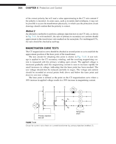
Method 2
An alternative method is to perform a primary injection test on one CT only, as shown
in Fig. 7.4.4. As with method 1, the ratio of primary to secondary test currents should
approximate to the transformer ratio marked on the nameplate. For multitapped CTs,
the ratio should be checked at each tap.
MAGNETISATION CURVE TESTS
The CT magnetisation curve should be checked at several points so as to establish the
approximate position of the knee point of the transformer.
The test circuit for obtaining this point is shown in Fig. 7.4.5. A test volt-
age is applied to the CT secondary winding, and the resulting magnetising cur-
rent is measured with the primary winding open circuit. The applied voltage is
increased gradually until the magnetising current is seen to increase rapidly for
small increases in voltage, indicating that the knee point has been reached. The
test voltage should then be reduced carefully in stages. The voltage and current
should be recorded at several points both above and below the knee point and
down to zero test voltage.
The knee point is defined as the point on the CT magnetisation curve where a
10% increase in applied voltage results in a 50% increase in magnetising current.
A B C
A 2
51
51
P 1 S 1 51
A 1 64
S 2
Temporary
short
Primary injection
test set
FIGURE 7.4.4
Circuit for current ratio check on current transformer by primary injection (method 2).