
Page 384 - Offshore Electrical Engineering Manual
P. 384
Protection Relays 371
Primary injection
test set
A 1 A 2
A 51
B 51
C 51
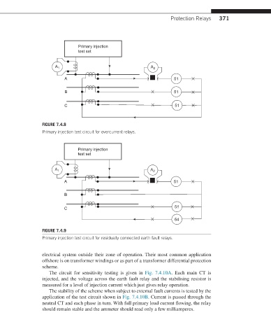
FIGURE 7.4.8
Primary injection test circuit for overcurrent relays.
Primary injection
test set
A 1 A 2
A 51
B
C 51
64
FIGURE 7.4.9
Primary injection test circuit for residually connected earth fault relays.
electrical system outside their zone of operation. Their most common application
offshore is on transformer windings or as part of a transformer differential protection
scheme.
The circuit for sensitivity testing is given in Fig. 7.4.10A. Each main CT is
injected, and the voltage across the earth fault relay and the stabilising resistor is
measured for a level of injection current which just gives relay operation.
The stability of the scheme when subject to external fault currents is tested by the
application of the test circuit shown in Fig. 7.4.10B. Current is passed through the
neutral CT and each phase in turn. With full primary load current flowing, the relay
should remain stable and the ammeter should read only a few milliamperes.