
Page 403 - Offshore Electrical Engineering Manual
P. 403
390 CHAPTER 1 Reliability
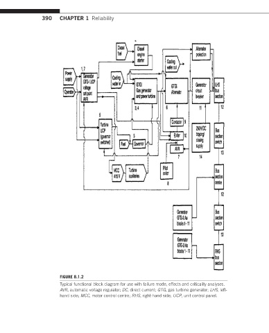
FIGURE 8.1.2
Typical functional block diagram for use with failure mode, effects and criticality analyses.
AVR, automatic voltage regulator; DC, direct current; GTG, gas turbine generator; LHS, left-
hand side; MCC, motor control centre; RHS, right-hand side; UCP, unit control panel.