
Page 407 - Offshore Electrical Engineering Manual
P. 407
394 CHAPTER 1 Reliability
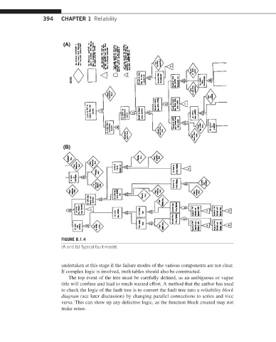
FIGURE 8.1.4
(A and B) Typical fault model.
undertaken at this stage if the failure modes of the various components are not clear.
If complex logic is involved, truth tables should also be constructed.
The top event of the tree must be carefully defined, as an ambiguous or vague
title will confuse and lead to much wasted effort. A method that the author has used
to check the logic of the fault tree is to convert the fault tree into a reliability block
diagram (see later discussion) by changing parallel connections to series and vice
versa. This can show up any defective logic, as the function block created may not
make sense.