
Page 44 - Oil and Gas Production Handbook An Introduction to Oil and Gas Production
P. 44
separator to about 3-5 MPa (30-50 times atmospheric pressure). Inlet
temperature is often in the range of 100-150 degrees C. On the example
platform, the well stream is colder due to subsea wells and risers.
The pressure is often
reduced in several
stages, in this instance
three stages are used
to allow the controlled
separation of volatile
components. The idea
is to achieve maximum
liquid recovery and
stabilized oil and gas
and to separate water.
A large pressure
reduction in a single separator will cause flash vaporization leading to
instability and safety hazards.
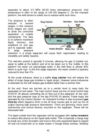
The retention period is typically 5 minutes, allowing the gas to bubble out,
water to settle at the bottom and oil to be taken out in the middle. In this
platform the water cut (percentage water in the well flow) is almost 40%
which is quite high. In the first stage separator, the water content is typically
reduced to less than 5%.
At the crude entrance, there is a baffle slug catcher that will reduce the
effect of slugs (large gas bubbles or liquid plugs). However some turbulence
is desirable as this will release gas bubbles faster than a laminar flow.
At the end, there are barriers up to a certain level to keep back the
separated oil and water. The main control loops are the oil level control loop
(EV0101 20 above) controlling the oil flow out of the separator on the right,
and the gas pressure loop at the top.(FV0105 20 above) These loops are
operated by the Control System. An important function is also to prevent gas
blow-by which happens when a low oil level causes gas to exit via the oil
output causing high pressure downstream. There are generally many more
instruments and control devices mounted on the separator. These will be
discussed later.
The liquid outlets from the separator will be equipped with vortex breakers
to reduce disturbance on the liquid table inside. This is basically a flange trap
to break any vortex formation and ensure that only separated liquid is tapped
off and not mixed with oil or water drawn in though these vortices. Similarly
42