
Page 114 - Op Amps Design, Applications, and Troubleshooting
P. 114
AC-Coupled Amplifier 97
RI and Q fonn an RC-coupling circuit on the input. That portion of the input sig-
nal that appears across RI is actually amplified by the circuit.
2.7.2 Numerical Analysis
Most of the calculations for the basic direct-coupled inverting and noninverting
amplifier circuits apply to the AC-coupled inverting and noninverting amplifier,
respectively. For purposes of our present analyses, we will determine the follow-
ing circuit parameters:
1. Voltage gain
2. Input impedance
3. Bandwidth
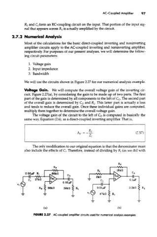
We will use the circuits shown in Figure 2.27 for our numerical analysis example.
Voltage Gain. We will compute the overall voltage gain of the inverting cir-
cuit, Figure 2.27(a), by considering the gain to be made up of two parts. The first
part of the gain is determined by all components to the left of C 0. The second part
of the overall gain is determined by C 0 and R L. This latter part is actually a loss
and tends to reduce the overall gain. Once these individual gains are computed,
multiply them together to determine the overall voltage gain.
The voltage gain of the circuit to the left of C 0 is computed in basically the
same way, Equation (2.6), as a direct-coupled inverting amplifier. That is,
The only modification to our original equation is that the denominator must
also include the effects of Q. Therefore, instead of dividing by R/ (as we did with
FIGURE 2.27 AC-coupled amplifier circuits used for numerical analysis examples.