
Page 110 - Op Amps Design, Applications, and Troubleshooting
P. 110
Noninverting Summing Amplifier 93
2.6 NONINVERTING SUMMING AMPLIFIER
2.6.1 Operation
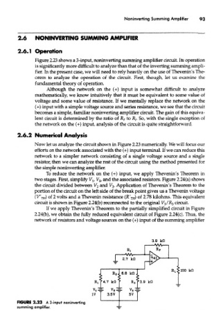
Figure 2.23 shows a 3-input, noninverting summing amplifier circuit. Its operation
is significantly more difficult to analyze than that of the inverting summing ampli-
fier. In the present case, we will need to rely heavily on the use of Thevenin's The-
orem to analyze the operation of the circuit. First, though, let us examine the
fundamental theory of operation.
Although the network on the (+) input is somewhat difficult to analyze
mathematically, we know intuitively that it must be equivalent to some value of
voltage and some value of resistance. If we mentally replace the network on the
(+) input with a simple voltage source and series resistance, we see that the circuit
becomes a simple, familiar noninverting amplifier circuit. The gain of this equiva-
lent circuit is determined by the ratio of R F to R/. So, with the single exception of
the network on the (+) input, analysis of the circuit is quite straightforward.
2.6.2 Numerical Analysis
Now let us analyze the circuit shown in Figure 2.23 numerically. We will focus our
efforts on the network associated with the (+) input terminal. If we can reduce this
network to a simpler network consisting of a single voltage source and a single
resistor, then we can analyze the rest of the circuit using the method presented for
the simple noninverting amplifier.
To reduce the network on the (+) input, we apply Thevenin's Theorem in
two stages. First, simplify V lf V 2, and the associated resistors. Figure 2.24(a) shows
the circuit divided between V 2 and V 3. Application of Thevenin's Theorem to the
portion of the circuit on the left side of the break point gives us a Thevenin voltage
(V' TH) of 2 volts and a Thevenin resistance (RVn) °f 2.78 kilohms. This equivalent
circuit is shown in Figure 2.24{b) reconnected to the original V 5/R^ circuit.
If we apply Thevenin's Theorem to the partially simplified circuit in Figure
2.24(b), we obtain the fully reduced equivalent circuit of Figure 2.24(c). Thus, the
network of resistors and voltage sources on the (+) input of the summing amplifier
FIGURE 2.23 A 3-input noninverting
summing amplifier.