
Page 113 - Op Amps Design, Applications, and Troubleshooting
P. 113
96 AMPLIFIERS
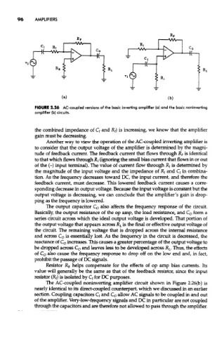
FIGURE 2.26 AC-coupled versions of the basic inverting amplifier (a) and the basic nontnverting
amplifier (b) circuits.
the combined impedance of C/ and R/) is increasing, we know that the amplifier
gain must be decreasing.
Another way to view the operation of the AC-coupled inverting amplifier is
to consider that the output voltage of the amplifier is determined by the magni-
tude of feedback current. The feedback current that flows through R? is identical
to that which flows through Rj (ignoring the small bias current that flows in or out
of the (-) input terminal). The value of current flow through R t is determined by
the magnitude of the input voltage and the impedance of RI and Q in combina-
tion. As the frequency decreases toward DC, the input current, and therefore the
feedback current, must decrease. This lowered feedback current causes a corre-
sponding decrease in output voltage. Because the input voltage is constant but the
output voltage is decreasing, we can conclude that the amplifier's gain is drop-
ping as the frequency is lowered.
The output capacitor C 0 also affects the frequency response of the circuit.
Basically, the output resistance of the op amp, the load resistance, and C 0 form a
series circuit across which the ideal output voltage is developed. That portion of
the output voltage that appears across R L is the final or effective output voltage of
the circuit. The remaining voltage that is dropped across the internal resistance
and across C o is essentially lost. As the frequency in the circuit is decreased, the
reactance of C 0 increases. This causes a greater percentage of the output voltage to
be dropped across C o and leaves less to be developed across JR L. Thus, the effects
of C o also cause the frequency response to drop off on the low end and, in fact,
prohibit the passage of DC signals.
Resistor R B helps compensate for the effects of op amp bias currents. Its
value will generally be the same as that of the feedback resistor, since the input
resistor (R/) is isolated by Q for DC purposes.
The AC-coupled noninverting amplifier circuit shown in Figure 2.26(b) is
nearly identical to its direct-coupled counterpart, which we discussed in an earlier
section. Coupling capacitors C/ and C 0 allow AC signals to be coupled in and out
of the amplifier. Very-low-frequency signals and DC in particular are not coupled
through the capacitors and are therefore not allowed to pass through the amplifier.