
Page 197 - Op Amps Design, Applications, and Troubleshooting
P. 197
180 OSCILLATORS
•f J~ 0,000 V
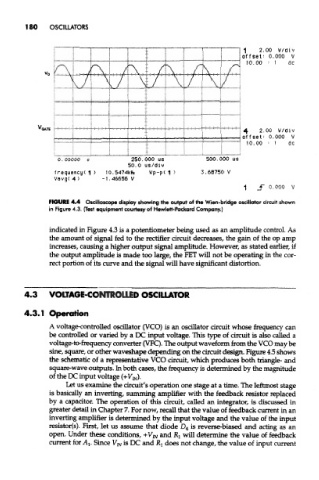
FIGURE 4.4 Oscilloscope display showing the output of the Wien-bridge oscillator circuit shown
in Figure 4.3. (Test equipment courtesy of Hewlett-Packard Company.)
indicated in Figure 4.3 is a potentiometer being used as an amplitude control. As
the amount of signal fed to the rectifier circuit decreases, the gain of the op amp
increases, causing a higher output signal amplitude. However, as stated earlier, if
the output amplitude is made too large, the PET will not be operating in the cor-
rect portion of its curve and the signal will have significant distortion.
4.3 VOLTAGE-CONTROLLED OSCILLATOR
4.3.1 Operation
A voltage-controlled oscillator (VCO) is an oscillator circuit whose frequency can
be controEed or varied by a DC input voltage. This type of circuit is also called a
voltage-to-frequency converter (VFC). The output waveform from the VCO may be
sine, square, or other waveshape depending on the circuit design. Figure 4.5 shows
the schematic of a representative VCO circuit, which produces both triangle- and
square-wave outputs. In both cases, the frequency is determined by the magnitude
of the DC input voltage (+F JN).
Let us examine the circuit's operation one stage at a time. The leftmost stage
is basically an inverting, summing amplifier with the feedback resistor replaced
by a capacitor. The operation of this circuit, called an integrator, is discussed in
greater detail in Chapter 7. For now, recall that the value of feedback current in an
inverting amplifier is determined by the input voltage and the value of the input
resistor(s). First, let us assume that diode D 4 is reverse-biased and acting as an
open. Under these conditions, +V iN and Rj will determine the value of feedback
current for AI. Since V IN is DC and RI does not change, the value of input current