
Page 26 - Op Amps Design, Applications, and Troubleshooting
P. 26
Review of Important Basic Concepts 9
In the case of Figure 1.6(c), we apply Equation (1.5) as
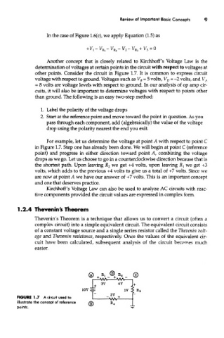
Another concept that is closely related to Kirchhoff's Voltage Law is the
determination of voltages at certain points in the circuit with respect to voltages at
other points. Consider the circuit in Figure 1.7. It is common to express circuit
voltage with respect to ground. Voltages such as V B = 5 volts, V D = -2 volts, and V A
- 8 volts are voltage levels with respect to ground. In our analysis of op amp cir-
cuits, it will also be important to determine voltages with respect to points other
than ground. The following is an easy two-step method:
1. Label the polarity of the voltage drops
2. Start at the reference point and move toward the point in question. As you
pass through each component, add (algebraically) the value of the voltage
drop using the polarity nearest the end you exit.
For example, let us determine the voltage at point A with respect to point C
in Figure 1.7. Step one has already been done. We will begin at point C (reference
point) and progress in either direction toward point A, combining the voltage
drops as we go. Let us choose to go in a counterclockwise direction because that is
we
the shortest path. Upon leaving JR 2 get +4 volts, upon leaving JR} we get +3
volts, which adds to the previous +4 volts to give us a total of +7 volts. Since we
are now at point A we have our answer of +7 volts. This is an important concept
and one that deserves practice.
Kirchhoff's Voltage Law can also be used to analyze AC circuits with reac-
tive components provided the circuit values are expressed in complex form.
1.2.4 Thevenin's Theorem
Thevenin's Theorem is a technique that allows us to convert a circuit (often a
complex circuit) into a simple equivalent circuit. The equivalent circuit consists
of a constant voltage source and a single series resistor called the Thevenin volt-
age and Thevenin resistance, respectively. Once the values of the equivalent cir-
cuit have been calculated, subsequent analysis of the circuit becomes much
easier.
FIGURE 1.7 A circuit used to
illustrate the concept of reference
points.