
Page 29 - Op Amps Design, Applications, and Troubleshooting
P. 29
12 BASIC CONCEPTS OF THE INTEGRATED OPERATIONAL AMPLIFIER
posed of a current source and a parallel resistance rather than a voltage source and
a series resistance like the Theve'nin equivalent. The sequential steps for obtaining
the Norton equivalent circuit are as follows:
1. Short all voltage sources and open all current sources (replace all sources
with their internal impedance if it is known). Also open the circuit at the
point of simplification.
2. Calculate the value of Norton's resistance as seen from the point of
simplification.
3. Replace the voltage and current sources with their original values and short
the circuit at the point of simplification.
4. Calculate Norton's current at the point of simplification.
5. Replace the original circuit components with the Norton's equivalent for
subsequent analysis of the circuit beyond the point of simplification.
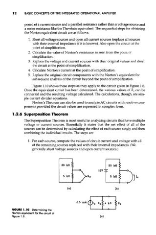
Figure 1.10 shows these steps as they apply to the circuit given in Figure 1.8.
Once the equivalent circuit has been determined, the various values of R x can be
connected and the resulting voltage calculated. The calculations, though, are sim-
ple current divider equations.
Norton's Theorem can also be used to analyze AC circuits with reactive com-
ponents provided the circuit values are expressed in complex form.
1.2.6 Superposition Theorem
The Superposition Theorem is most useful in analyzing circuits that have multiple
voltage or current sources. Essentially it states that the net effect of all of the
sources can be determined by calculating the effect of each source singly and then
combining the individual results. The steps are
1. For each source, compute the values of circuit current and voltage with all
of the remaining sources replaced with their internal impedances. (We
generally short voltage sources and open current sources.)
FIGURE 1.10 Determining the
Norton equivalent for the circuit of
Figure 1.8.