
Page 33 - Op Amps Design, Applications, and Troubleshooting
P. 33
16 BASIC CONCEPTS OF THE INTEGRATED OPERATIONAL AMPLIFIER
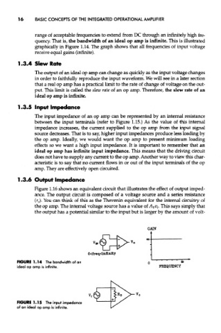
range of acceptable frequencies to extend from DC through an infinitely high fre-
quency. That is, the bandwidth of an ideal op amp is infinite. This is illustrated
graphically in Figure 1.14. The graph shows that all frequencies of input voltage
receive equal gains (infinite).
1.3.4 Slew Rate
The output of an ideal op amp can change as quickly as the input voltage changes
in order to faithfully reproduce the input waveform. We will see in a later section
that a real op amp has a practical limit to the rate of change of voltage on the out-
put. This limit is called the slew rate of an op amp. Therefore, the slew rate of an
ideal op amp is infinite.
The input impedance of an op amp can be represented by an internal resistance
between the input terminals (refer to Figure 1.15.) As the value of this internal
impedance increases, the current suppEed to the op amp from the input signal
source decreases. That is to say, higher input impedances produce less loading by
the op amp. Ideally, we would want the op amp to present minimum loading
effects so we want a high input impedance. It is important to remember that an
ideal op amp has infinite input impedance. This means that the driving circuit
does not have to supply any current to the op amp. Another way to view this char-
acteristic is to say that no current flows in or out of the input terminals of the op
arnp. They are effectively open circuited.
1.3.6 Output Impedance
Figure 1.16 shows an equivalent circuit that illustrates the effect of output imped-
ance. The output circuit is composed of a voltage source and a series resistance
(r 0). You can think of this as the Thevenin equivalent for the internal circuitry of
the op amp. The internal voltage source has a value of A vv t. This says simply that
the output has a potential similar to the input but is larger by the amount of volt-
FIGURE 1.14 The bandwidth of an
ideal op amp is infinite.
FIGURE 1.15 The input impedance
of an ideal op amp is infinite.