
Page 35 - Op Amps Design, Applications, and Troubleshooting
P. 35
18 BASIC CONCEPTS OF THE INTEGRATED OPERATIONAL AMPLIFIER
1.3.9 Troubleshooting Tips
Even though we have barely begun to discuss op amps and how they work, we
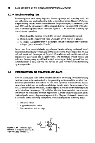
can still extend our troubleshooting skills to include op amps. Figure 1.17 shows a
simple op amp circuit. Notice the addition of the power supply connections (+15V
and -15V) and the pin numbers of the integrated circuit package (741). With refer-
ence to the ideal op amp circuit shown in Figure 1.17, we know the following rep-
resent normal operation:
1. There should be positive 15 volts DC on pin 7 with respect to ground.
2. There should be negative 15 volts DC on pin 4 with respect to ground.
3. As long as V,- is greater than 0, the output should be at either of two extreme
voltages (approximately ±15 volts).
Items 1 and 2 are essential checks regardless of the circuit being evaluated. Item 3
results from the infinite voltage gain of the ideal op amp. If you applied an AC sig-
nal and monitored the output of Figure 1.17 (under normal conditions) with an
oscilloscope, you would see a square wave. The amplitude would be near ±15
volts and the frequency would be identical to the input. Satisfy yourself that this
latter statement is true, and you will be well on your way toward understanding
op amp operation.
1.4 INTRODUCTION TO PRACTICAL OP AMPS
Now let us consider some of the nonideal effects of an op amp. By understanding
the ideal characteristics described in the preceding sections and the nonideal char-
acteristics presented in this section, we will be in a position to evaluate and discuss
these characteristics as we analyze and design the circuits in the remainder of this
text. As the circuits are presented, an ideal approach will be used whenever practi-
cal to introduce the concept. We will then identify those nonideal characteristics
that should be considered for each application. A more detailed discussion of the
nonideal performance of op amps is presented in Chapter 10. As each characteristic
is discussed in the following paragraphs, we will compare the following items:
1. The ideal value
2. A typical nonideal value
3. The value for a real op amp
FIGURE 1.17 Schematic repre-
sentation of an op amp showing the
± power supply connections.