
Page 31 - Op Amps Design, Applications, and Troubleshooting
P. 31
14 BASIC CONCEPTS OF THE INTEGRATED OPERATIONAL AMPLIFIER
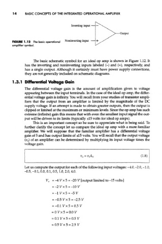
FIGURE 1.12 The basic operational
amplifier symbol.
The basic schematic symbol for an ideal op amp is shown in Figure 1.12. It
has the inverting and noninverting inputs labeled (-) and (+)/ respectively, and
has a single output. Although it certainly must have power supply connections,
they are not generally included on schematic diagrams.
1.3.1 Differential Voltage Gain
The differential voltage gain is the amount of amplification given to voltage
appearing between the input terminals. In the case of the ideal op amp, the differ-
ential voltage gain is infinity. You will recall from your studies of transistor ampli-
fiers that the output from an amplifier is limited by the magnitude of the DC
supply voltage. If an attempt is made to obtain greater outputs, then the output is
clipped or limited at the maximum or minimum levels. Since the op amp has such
extreme (infinite) gain this means that with even the smallest input signal the out-
put will be driven to its limits (typically ±15 volts for ideal op amps).
This is an important concept so be sure to appreciate what is being said. To
further clarify the concept let us compare the ideal op amp with a more familiar
amplifier. We will suppose that the familiar amplifier has a differential voltage
gain of 5 and has output limits of ±15 volts. You will recall that the output voltage
(v 0) of an amplifier can be determined by multiplying its input voltage times the
voltage gain.
Let us compute the output for each of the following input voltages: -4.0, -2.0, -1.0,
-0.5, -0.1, 0.0, 0.1, 0.5,1.0,2.0,4.0.