
Page 55 - Op Amps Design, Applications, and Troubleshooting
P. 55
38 AMPLIFIERS
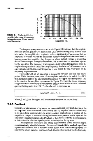
FIGURE 2.1 The bandwidth of an
amplifier is the range of frequencies
between the upper (f u) and lower (fj
cutoff frequencies.
The frequency response curve shown in Figure 2.1 indicates that the amplifier
provides greater gain for low frequencies. Once the input frequency exceeds a cer-
tain value, the amplification begins to reduce significantly. Frequencies that are
amplified to within 3 dB of the maximum output voltage level are considered as
having passed the amplifier. Any frequency whose output voltage is lower than
the maximum output voltage by more than 3 dB is considered to have been rejected
by the amplifier. The frequency that separates the passband frequencies from the
stopband frequencies is called the cutoff frequency. And since -3 dB corresponds to
a power ratio of 0.5, the cutoff frequency is also called the half-power point on the
frequency response curve.
The bandwidth of an amplifier is measured between the two half-power
points. If the frequency response of an amplifier extends to include 0 (i.e., DC),
then the bandwidth of the amplifier is the same as the upper cutoff frequency. This
is the case for the amplifier represented in Figure 2.1. Here the lower frequency
range extends all the way to 0, but in many circuits there will be a lower cutoff fre-
quency that is greater than DC. The bandwidth is expressed as
where/u and/ L are the upper and lower cutoff frequencies, respectively.
2.1.3 Feedback
So far in our discussions of op amps, we have considered only the behavior of the
op amp itself with no external components. The op amp has been examined only
in its open-loop configuration. In most practical applications, a portion of the
amplifier's output is returned through external components to the input of the
amplifier. The return signal, called feedback, is then mixed with the incoming signal
to determine the effective signal applied to the input of the op amp.
The amplitude, frequency, and phase characteristics of the feedback signal
can dramatically alter the behavior of the overall circuit. If the feedback signal has
a phase relationship that is additive when mixed with the incoming signal, we
refer to the return signal as positive feedback. On the other hand, if the feedback sig-