
Page 56 - Op Amps Design, Applications, and Troubleshooting
P. 56
Inverting Amplifier 39
nal is out of phase (optimally 180 degrees) with the input signal, then the effective
input signal is reduced and we label it negative feedback. Both forms of feedback are
useful in certain op amp applications, but for the remainder of this chapter we will
limit our attention to negative feedback.
The external components that provide the feedback path may be frequency
selective. That is, if some frequencies pass through the feedback circuit with less
attenuation than other frequencies, then we have frequency-selective feedback.
This is a very useful form of feedback, but for the remainder of this chapter we
will limit our discussion to nonselective feedback methods.
2.2 INVERTING AMPLIFIER
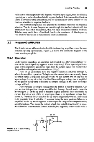
The first circuit we will examine in detail is the inverting amplifier, one of the most
common op amp applications. Figure 2.2 shows the schematic diagram of the
basic inverting amplifier.
2.2.1 Operation
Under normal operation, an amplified but inverted (i.e., 180° phase shifted) ver-
sion of the input signal (v }) appears at the output (v o). If the input signal is too
large or the amplifier's gain is too high, then the output signal will be clipped at
the positive and negative saturation levels (±V SAr).
Now let us understand how the negative feedback returned through R F
affects the amplifier operation. To begin our discussion, let us momentarily freeze
the input signal as it passes through 0 volts. At this instant, the op amp has no
input voltage (i.e., V D = 0 volts). It is this differential input voltage that is amplified
by the gain of the op amp to become the output voltage. In this case, the output
voltage will be 0.
Now suppose the output voltage tried to drift in a positive direction. Can
you see that this positive change would be felt through R F and would cause the
inverting pin (-) of the op amp to become slightly positive? Since essentially no
current flows in or out of the op amp input, there is no significant voltage drop
across jR B. Therefore the (+) input of the op amp is at ground potential. This causes
V D to be greater than 0 with the (-) terminal being the most positive. When V D is
amplified by the op amp it appears in the output as a negative voltage (inverting
amplifier action). This forces the output, which had initially tried to drift in a pos-
itive direction, to return to its 0 state. A similar, but opposite, action would occur if
FIGURE 2.2 A basic inverting
amplifier circuit.