
Page 68 - Op Amps Design, Applications, and Troubleshooting
P. 68
Inverting Amplifier 51
With this small value of load resistance, we would not be able to provide full-
range voltage swings on the output because of excessive loading.
In the foregoing calculations (as with most calculations presented in this
book), it is not important to remember all of the equations. Rather, strive to under-
stand the concept and realize that most of what we are discussing is centered on
basic electronics principles that you learned when you studied introductory AC
and DC circuits.
Bandwidth. Although the bandwidth of an ideal op amp is considered to be
infinite, the bandwidth of real op amps and the associate amplifier circuit are def-
initely restricted. In the case of the circuit shown in Figure 2.3, the lower cutoff fre-
quency is essentially 0. That is, since the op amp responds all the way down to
DC, and since there are no reactive components to reject the lower frequencies, the
amplifier circuit will operate with frequencies as low as DC.
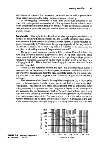
The upper cutoff frequency is quite a different story. Figure 2.6 shows the
open-loop frequency response (upper curve) for a 741 op amp. This is the same
curve presented in the manufacturer's data sheet as open-loop voltage gain as a
function of frequency. Also drawn on the graph in Figure 2.6 is a line showing a
voltage gain of 12.2. This is the ideal closed-loop gain that we calculated for the
circuit in Figure 2.3.
Notice that the difference between the open- and closed-loop gain curves is
maximum at low frequencies. As the frequency increases, the difference between
the two curves becomes less. Near the right side of the graph, the two curves actu-
ally intersect. What really happens to the overall circuit gain as the frequency
increases?
The derivation of the formula for amplifier voltage gain (A v = -R F/R f) was
based on the assumption that the op amp had an infinite (or at least a very high)
voltage gain. This allowed us to make the assumption that the differential input
voltage (%) was 0. As you can see from the graph in Figure 2.6, our assumptions
are reasonable for low frequencies. That is, the open-loop voltage gain is very
high. But as the frequency increases and the open-loop gain rolls off, our assump-
tions begin to lose their validity. The most obvious proof of this exists beyond the
point of intersection of the open- and closed-loop curves. In the region to the right
of the intersection point, the open-loop gain is actually lower than our calculated
l.OM 10M
FIGURE 2.6 Frequency response of
the standard 741 op amp.