
Page 69 - Op Amps Design, Applications, and Troubleshooting
P. 69
AMPLIFIERS
closed-loop gain, thus making it impossible for our circuit to deliver the desired
amplification.
It is common to compute bandwidth in a circuit like that shown in Figure 2.3
by applying the following equation:
where fuG is the unity gain frequency of the op amp. Substituting values and com-
puting gives us the following:
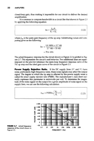
The actual frequency response for the circuit shown in Figure 2.3 is plotted in Fig-
ure 2.7. This represents the circuit's real behavior. Two additional lines are super-
imposed on the plot for reference: the open-loop frequency response curve of the
741 op amp and the ideal gain curve of the circuit in Figure 2.3.
+
Power Supply Rejection Ratio. If the DC supply lines (V and V") have
noise, particularly high-frequency noise, these noise signals may affect the output
signal. The degree to which the op amp is affected by the power supply noise is
called the power supply rejection ratio (PSRR). The manufacturer's data sheet nor-
mally expresses this parameter in microvolts per volt. To determine the magni-
tude of the noise signal on the output for a given amplitude of noise signal on the
supply lines, we can use the following calculation:
FIGURE 2.7 Actual frequency
l.OM 10M
response of the circuit shown in
Figure 2.3.