
Page 64 - Op Amps Design, Applications, and Troubleshooting
P. 64
Inverting Amplifier 47
Next compute the effective output impedance with Equation (2.15):
This low value approaches our ideal value of 0 ohms. Now, as an illustration,
recompute the value of output impedance at a higher frequency of 5 kilohertz.
First compute A OL with Equation (2.16).
Next compute the effective output impedance with Equation (2.15).
This value is significantly higher than our first estimate and clearly shows
the increase in output resistance as the input frequency is increased.
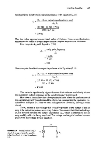
How does a particular value of output impedance affect the performance of
the amplifier circuit? To understand the effects, we can examine the equivalent cir-
cuit shown in Figure 2.4. Here we see a voltage source labeled v o driving a series
circuit.
The v o source is that voltage that would be present at the output of the op
amp if the output impedance were truly 0 ohms. You can see that this ideal voltage
(v o) is divided between the output impedance (r 0), which is internal to the op
amp, and R L, which is the op amp load. The voltage reaching the load can be com-
puted with the voltage divider equation.
FIGURE 2.4 The equivalent output
circuit of an op amp can be used to
judge the effects of output impedance
fro)-