
Page 70 - Op Amps Design, Applications, and Troubleshooting
P. 70
Inverting Amplifier 53
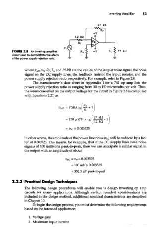
FIGURE 2.8 An inverting amplifier
circuit used to demonstrate the effects
of the power supply rejection ratio.
where V NO, v Nl R F, R 7, and PSRR are the values of the output noise signal, the noise
signal on the DC supply lines, the feedback resistor, the input resistor, and the
power supply rejection ratio, respectively. For example, refer to Figure 2.8.
The manufacturer's data sheet in Appendix 1 for a 741 op amp lists the
power supply rejection ratio as ranging from 30 to 150 microvolts per volt. Thus,
the worst-case effect on the output voltage for the circuit in Figure 2.8 is computed
with Equation (2.23) as
= V N x 0.003525
In other words, the amplitude of the power line noise (V N) will be reduced by a fac-
tor of 0.003525. This means, for example, that if the DC supply lines have noise
signals of 100 millivolts peak-to-peak, then we can anticipate a similar signal in
the output with an amplitude of about
2.2.3 Practical Design Techniques
The following design procedures will enable you to design inverting op amp
circuits for many applications. Although certain nonideal considerations are
included in the design method, additional nonideal characteristics are described
in Chapter 10.
To begin the design process, you must determine the following requirements
based on the intended application:
1. Voltage gain
2. Maximum input current