
Page 89 - Op Amps Design, Applications, and Troubleshooting
P. 89
72 AMPLIFIERS
A slight phase shift can be seen between input and output waveforms in Fig-
ure 2.15. The effect is more pronounced as the input frequency is increased. For
many applications, input/output phase relations are not important; in other
applications they are critical. Chapter 10 discusses this issue in more detail.
2.4 VOLTAGE FOLLOWER
2.4.1 Operation
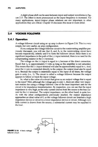
A voltage follower circuit using an op amp is shown in Figure 2.16. This is a very
simple, but very useful, op amp configuration.
If you compare the voltage follower circuit to the noninverting amplifier pre-
viously discussed, you will see that R, and R F in the noninverting circuit have
become respectively, infinity and 0 to form the follower circuit. Since there is no
significant impedance in the path of the (-) input terminal, there is no need for the
compensating resistor in the (+) terminal.
The voltage on the (+) input is equal to i?/ because of the direct connection.
Recall that V D is approximately 0 volts as long as the amplifier is not saturated.
This means that the (-) input terminal will also be approximately equal to v t. And,
since the (-) pin is connected directly to the output, the output must also be equal
to z?/. Because the output is essentially equal to the input at all times, the voltage
gain is unity (i.e., 1). The circuit is called a voltage follower because the output
appears to follow or track the input voltage.
So, what is the value of a circuit that gives us an output voltage that is equal
to the input? Well, although the voltage gain is only 1, there are other very impor-
tant reasons for using a voltage follower. One of the most important uses for the
circuit is for impedance transformation. By inspection, you can see that the input
impedance is very high, as the only current drawn from the source is the bias cur-
rent for the (+) terminal. The output impedance, on the other hand, is quite low.
As with the other configurations previously studied, the output impedance
approaches an ideal value of 0, so the voltage follower circuit can interface a high
impedance device or circuit to a lower impedance device or circuit. Although very
little current is drawn from the source, a substantial current may be supplied to
the load,
FIGURE 2.16 A basic voltage
follower circuit.