
Page 94 - Op Amps Design, Applications, and Troubleshooting
P. 94
Voltage Follower 77
1. Input voltage range 100 to 500 millivolts RMS
2. Frequency range DC to 75 kilohertz
3. Load resistance 4.7 kilohms
4. Input resistance greater than 100 kilohms
5. Source impedance 1.8 kilohms
Select the Op Amp. First, we must select an op amp that can provide unity
gain up to the maximum input frequency. That means we will need an op amp
with a unity gain bandwidth of at least Equation (2.32):
Second, the slew rate of the op amp must be adequate to allow the required output
voltage swing at the highest input frequency. The required slew rate is given by
Equation (2.11):
Since both the unity gain frequency and the slew rate requirements are within the
limits of the 741 (see Appendix 1), let us choose this device for our design.
Select the Power Supply Voltages. Now we must select a power supply volt-
age that is high enough to prevent saturation on the highest input voltage. The worst-
case internal voltage drop on the output for a 741 is listed as 5 volts in Appendix 1 for
load resistances between 2 and 10 kilohms. A more typical value is 2 volts. The mini-
mum required power supply voltage can be determined as in Equation (2.25):
= 500mVx 1.414 +5 V
= 5.707 V
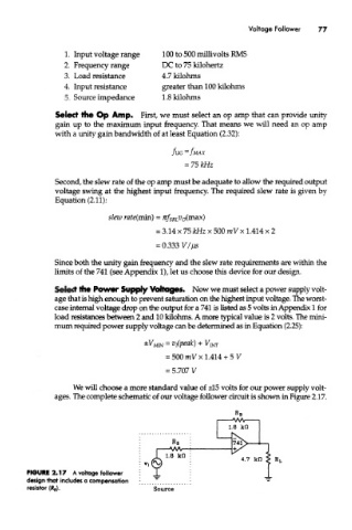
We will choose a more standard value of ±15 volts for our power supply volt-
ages. The complete schematic of our voltage follower circuit is shown in Figure 2.17.
FIGURE 2.17 A voltage follower
design that includes a compensation
resistor (R B ).