
Page 99 - Op Amps Design, Applications, and Troubleshooting
P. 99
82 AMPLIFIERS
27 ka
jR /4
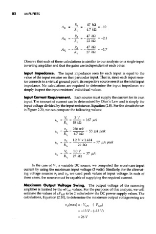
Observe that each of these calculations is similar to our analysis on a single-input
inverting amplifier and that the gains are independent of each other.
Input Impedance. The input impedance seen by each input is equal to the
value of the input resistor on that particular input. That is, since each input resis-
tor connects to a virtual ground point, its respective source sees it as the total input
impedance. No calculations are required to determine the input impedance; we
simply inspect the input resistors' individual values.
Input Current Requirement. Each source must supply the current for its own
input. The amount of current can be determined by Ohm's Law and is simply the
input voltage divided by the input resistance, Equation (2.8). For the circuit shown
in Figure 2.20, we can compute the following values:
In the case of V lt a variable DC source, we computed the worst-case input
current by using the maximum input voltage (3 volts). Similarly, for the alternat-
ing voltage sources v 2 and v 3, we used peak values of input voltage. In each of
these cases, the source must be capable of supplying the required current.
Maximum Output Voltage Swing. The output voltage of the summing
amplifier is limited by the ±V SAT values. For the purposes of this analysis, we will
estimate the values of ±V SAT to be 2 volts below the DC power supply values. The
calculations, Equation (2.10), to determine the maximum output voltage swing are