
Page 104 - Op Amps Design, Applications, and Troubleshooting
P. 104
Inverting Summing Amplifier 87
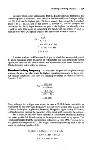
We know from earlier calculations that the bandwidth will decrease as the
closed-loop gain is increased. Let us calculate the bandwidth for the input in Fig-
ure 2.20 that has the highest gain. We have already determined the individual
gains to be 2.6, 10, 2.1, and 1.7 for inputs V l through V 4. We will compute the
bandwidth for the v 2 input because its gain is the highest. Incidentally, there
would be very little point in computing the bandwidth for inputs V } and V 4
because these have DC signals applied. The bandwidth for the v 2 input is
A similar analysis could be made for input v 3, which has a computed gain of
2.1 and a maximum input frequency of 10 kilohertz. For large amplitude output
signals, the slew rate will tend to restrict the operation to even lower frequencies,
This is discussed in the following section.
Slew-Role Limiting Frequency. As discussed for previous amplifier config-
urations, the slew rate also limits the highest operating frequency for larger out-
put voltage excursions. The slew-rate limiting frequency is found as follows,
Equation (2.11):
Thus, although the v 2 input was shown to have a 90.9-kilohertz bandwidth as
established by the unity gain frequency, the full-power upper limit is only 6.12
kilohertz. In the given application, however, the applied signal is only 5000 hertz,
so this should not hamper the operation of the circuit with respect to the v 2 input.
The E> 3 input, on the other hand, operates at 10 kilohertz. This means that we
can never get the full 26-volt swing in the output as a result of v 3 signals. The
schematic indicates that the highest input voltage is 1.2 volts RMS. The gain for v 3
was previously computed as 2.1. The largest normal output swing from v 3 can be
found by applying Equation (2.1):