
Page 97 - Op Amps Design, Applications, and Troubleshooting
P. 97
80 AMPLIFIERS
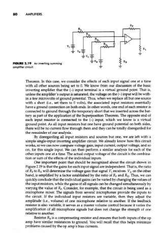
FIGURE 2.19 An inverting summing
amplifier circuit.
Theorem. In this case, we consider the effects of each input signal one at a time
with all other sources being set to 0. We know from our discussion of the basic
inverting amplifier that the (-) input terminal is a virtual ground point. That is,
unless the amplifier's output is saturated, the voltage on the (-) input will be with-
in a few microvolts of ground potential. Thus, when we replace all but one source
with a short (i.e., set them to 0 volts), the associated input resistors essentially
have a ground connection on both ends. In other words, one end of each resistor is
connected to ground through the temporary short that we inserted across the bat-
tery as part of the application of the Superposition Theorem. The opposite end of
each input resistor is connected to the (-) input, which we know is a virtual
ground point. As all input resistors but one have ground potential on both sides,
there will be no current flow through them and they can be totally disregarded for
the remainder of our analysis.
By disregarding all input resistors and sources but one, we are left with a
simple single-input inverting amplifier circuit. We already know how this circuit
works, so we can now compute voltage gain, input current, output voltage, and so
on, for this single input. We can then perform a similar analysis for each of the
other inputs one at a time. The actual output voltage of the circuit is the combina-
tion or sum of the effects of the individual inputs.
One important point that should be recognized about the circuit shown in
Figure 2.19 is that the gains for each input signal are independent. That is, the ratio
of R f to R n will determine the voltage gain that signal V l receives. V 2f on the other
hand, is amplified by a factor established by the ratio of R F and R n- Thus, we can
quickly conclude that the individual gains can be varied by changing the values of
the input resistors, while the gains of all signals can be changed simultaneously by
varying the value of R F. Consider, for example, that the circuit is being used as a
microphone mixer. The signals from several microphones provide the inputs to
the circuit. If the individual input resistors are variable, then they adjust the
amplitude (i.e., volume) of one microphone relative to another. If the feedback
resistor is also variable, it serves as a master volume control because it varies the
amplification of all microphone signals but does not change the strength of one
relative to another.
Resistor R B is a compensating resistor and ensures that both inputs of the op
amp have similar resistances to ground. You will recall that this helps minimize
problems caused by the op amp's bias currents.