
Page 101 - Optical Communications Essentials
P. 101
Light Sources and Transmitters
Light Sources and Transmitters 91
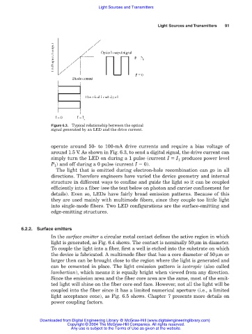
Figure 6.3. Typical relationship between the optical
signal generated by an LED and the drive current.
operate around 50- to 100-mA drive currents and require a bias voltage of
around 1.5 V. As shown in Fig. 6.3, to send a digital signal, the drive current can
simply turn the LED on during a 1 pulse (current I I 1 produces power level
P 1 ) and off during a 0 pulse (current I 0).
The light that is emitted during electron-hole recombination can go in all
directions. Therefore engineers have varied the device geometry and internal
structure in different ways to confine and guide the light so it can be coupled
efficiently into a fiber (see the text below on photon and carrier confinement for
details). Even so, LEDs have fairly broad emission patterns. Because of this
they are used mainly with multimode fibers, since they couple too little light
into single-mode fibers. Two LED configurations are the surface-emitting and
edge-emitting structures.
6.2.2. Surface emitters
In the surface emitter a circular metal contact defines the active region in which
light is generated, as Fig. 6.4 shows. The contact is nominally 50µm in diameter.
To couple the light into a fiber, first a well is etched into the substrate on which
the device is fabricated. A multimode fiber that has a core diameter of 50µmor
larger then can be brought close to the region where the light is generated and
can be cemented in place. The light emission pattern is isotropic (also called
lambertian), which means it is equally bright when viewed from any direction.
Since the emission area and the fiber core area are the same, most of the emit-
ted light will shine on the fiber core end face. However, not all the light will be
coupled into the fiber since it has a limited numerical aperture (i.e., a limited
light acceptance cone), as Fig. 6.5 shows. Chapter 7 presents more details on
power coupling factors.
Downloaded from Digital Engineering Library @ McGraw-Hill (www.digitalengineeringlibrary.com)
Copyright © 2004 The McGraw-Hill Companies. All rights reserved.
Any use is subject to the Terms of Use as given at the website.