
Page 140 - Optical Communications Essentials
P. 140
Connectors and Splices
130 Chapter Eight
8.5.1. Design requirements
Some principal requirements of good connector design are as follows:
■ Coupling loss. The connector assembly must maintain stringent alignment
tolerances to ensure low mating losses. The losses should be around 2 to 5 per-
cent (0.1 to 0.2dB) and must not change significantly during operation and
after numerous connects and disconnects.
■ Interchangeability. Connectors of the same type must be compatible from one
manufacturer to another.
■ Ease of assembly. A service technician should be able to install the connector
in a field environment, that is, in a location other than the connector attach-
ment factory.
■ Low environmental sensitivity. Conditions such as temperature, dust, and
moisture should have a small effect on connector loss variations.
■ Low cost and reliable construction. The connector must have a precision suit-
able to the application, but it must be reliable and its cost must not be a major
factor in the system.
■ Ease of connection. Except for certain unique applications, one should be able
to mate and disconnect the connector simply and by hand.
8.5.2. Connector components
Connectors are available in designs that screw on, twist on, or snap in place.
The twist-on and snap-on designs are the ones used most commonly. The
designs include both single-channel and multichannel assemblies for cable-to-
cable and cable-to-circuit-card connections.
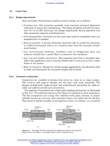
The majority of connectors use a butt-joint coupling mechanism, as illustrated
in Fig. 8.11. The elements shown in this figure are common to most connectors.
The key components are a long, thin stainless steel, glass, ceramic, or plastic
cylinder, known as a ferrule, and a precision sleeve into which the ferrule fits.
This sleeve is known variably as an alignment sleeve, an adapter, or a coupling
Figure 8.11. Example ferrules inserted into alignment sleeves for precision
alignment of two fibers: (a) straight sleeve and (b) tapered sleeve.
Downloaded from Digital Engineering Library @ McGraw-Hill (www.digitalengineeringlibrary.com)
Copyright © 2004 The McGraw-Hill Companies. All rights reserved.
Any use is subject to the Terms of Use as given at the website.